IntroductionThe development of commercial air bearing machining spindles has been largely driven by the growth in the number of applications for high and ultra precision machining as well as the continual need for higher standards of machine performance. The diversity in the range of high precision machining applications has lead to an almost equally diverse range of spindles, highly customised and incorporating a host of special features. For example all air bearing machining spindles have integral drive motors but now they may be frame or frameless, AC or DC brushless, air or watercooled. Spindles may include encoders or resolvers for accurate synchronisation of rotation with other machine functions whilst work/tool holding may be faceplates, collets or airchucks, manually or automatically operated. Through shaft coolant feeds, air turbine drives and integral linear slideways are amongst other special features sometimes required. High precision machining spindles are characterised by the performance parameters:- low motion error, high static and dynamic stiffness and low thermal growth. Improvements in these parameters have resulted from increased customisation, tailoring spindle layouts to individual requirements; increased integration of auxiliary components and hence better optimisation of the overall system as well as incremental developments in bearing design and the manufacturing process. In this article some of the developments contributing to improved spindle performance are discussed and examples of practical spindles described. Spindle PerformanceAlthough there are a variety of bearing geometry’s used for high precision machining attention is confined to an arrangement comprising of cylindrical journal and plain thrust bearings. Cylindrical and flat, annular bearing geometry’s can be manufactured to the high standard of precision and finish essential for low motion errors. They also exhibit low thermal distortion that means they are suitable for both high and low speed operation. Bearing Stiffness - However speeds in the vast majority of high precision machining applications are modest and the emphasis on bearing design is usually to achieve maximum static stiffness for the required speed range. The stiffness of an air bearing is inversely proportional to its internal clearance and therefore maximum stiffness is achieved by minimising clearance. But there are limits to how far clearance can be reduced, one is thermal distortion the other is the geometrical accuracy to which the bearings can be manufactured. Thermal distortion arises from small frictional losses in the bearings and somewhat larger power losses in the drive motor, both of which increase with speed. On most spindles, heat losses from housings are higher than those from shafts and a temperature gradient is set up across the bearings that reduces their clearance. Whilst water cooling may effectively control spindle housing temperatures and overall spindle growth, temperature gradients across the bearings are not necessarily reduced and may even be increased. Allowing for thermal distortion, bearing clearances cannot be reduced to the extent that opposing surfaces come into contact under operational conditions and in practice the bearing is designed to take maximum load at a safe working gap. The larger the surface geometry errors, the larger this gap and the bearing design clearance. Over the last 20 years bearing clearances on high precision air spindles have been reduced by approximately 40 % and is one of the reasons why higher stiffnesses are now being achieved. The reductions are due mostly to improved manufacturing methods and better understanding of thermal distortion. Improvements in the internal design of the bearing have also benefited stiffness. Essentially these are due to more sophisticated computer models predicting more accurately the effects of air flow through feed orifices and the bearing gap. Early bearing designs were based upon one dimensional air flow models, whereas now two dimensional models include effects such as the cross flow of air around journal bearings and dispersion of air out of feed orifices, thus enabling better optimisation of the air feed arrangement.
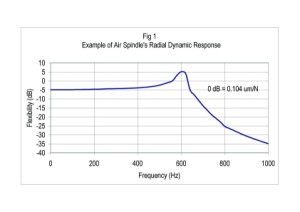
Spindle Stiffness and Damping - Overall radial stiffness of the spindle depends not only on the bearings but the spindle layout and the rigidity of other components such as the shaft and work holding arrangement. Computer models for determining the elastic deformation of a bearing – shaft system have enabled better optimisation of the spindle layout, minimising the cantilevering effect of an overhung work position. The models have also been vital in improving the dynamic behaviour of spindles. Critical speeds in the operating speed range can usually be avoided and dynamic stiffness at the work position optimised by judicial choice of system parameters. Fig 1 is an example of the radial dynamic response of a lens turning spindle measured at the work position. This spindle operates and speeds of up to 10 000 rpm and the first critical speed occurs at 295 Hz. The magnitude of the response at 610 Hz defines the dynamic stiffness of the spindle which in this case is 5.3 N/um and compares to a static stiffness of 17.2 N/um. Dynamic stiffness of an air spindle is mostly dependent on bearing damping and the typical response of fig 1 shows this to be high compared to the level of damping found in most mechanical structures. Motion Error – Is normally characterised by three parameters, basic eccentricity, higher order synchronous motion errors and asynchronous motion errors. These parameters are measured in both axial and radial directions. In general, air spindle motion error is primarily a function of the bearings, magnetic imbalance in the motor and mechanical out of balance. Many ultraprecision machining applications now require peak–peak motion errors lower than 0.05 um so all three sources are critically important. The basic eccentricity in motion error is normally controlled by attention to bearing alignments and out of balance. Micron level manufacturing precision and two plane balancing to a high standard, ie ISO1940-1973 G0.4 is generally necessary to meet the more demanding specifications. Air bearings can produce both synchronous and asynchronous motion. On stable bearing designs the latter is normally low in level and is mostly a function of the bearing air. Ensuring that the supply air is free from pressure pulses and contaminants is essential for low asynchronous motion error. Minimisation of air turbulence within the bearing and random pressure fluctuations in the exhaust air can also help to reduce asynchronous motion errors. Synchronous motion errors arise if the bearing geometry departs from perfect round, (or flat in the case of a thrust bearing),.The air film in an air bearing averages the effect of bearing geometry errors to a low level and ratios of motion error/geometry error as low as 0.05 have been observed in practice. However sub micron precision of bearing surfaces is still required to meet most ultraprecision motion specifications. Improvements in manufacturing methods have had an important effect on motion error and have enabled errors to be reduced from about 0.2 um typical on commercial machining spindles 20 years ago to the present level of 0.05 um peak-peak. Motion errors arising from drive motors are usually dominated by synchronous movements characterised by harmonics of pole passing frequency. Asynchronous motion errors can occur but are usually low in level. Magnetic forces necessary to produce required drive torques are high and although motors have poles arranged opposite each other to balance out the forces there are several factors which can leave a residual magnetic imbalance. Thus on air spindles fitted with integral frameless motors the motion errors which can result are determined by the magnitude of the forces and the stiffness of the air bearings. High precision air spindles may also use self contained precision motors mounted inline at the rear of the spindle. Such motors benefit from the additional stiffness of precision grade ball bearings that are effective in limiting the motion errors due to magnetic forces. The ball bearings can be a source of motion error but vibration forces are generally small compared to those that would otherwise result from magnetic imbalance and are isolated from the air spindle by a flexible coupling. From the point of view of reducing magnetic imbalance, motor design and manufacturing methods have improved significantly during the last 10 years with the result that now both frame and frameless motors with imbalanced magnetic forces of less than 1 N can be obtained. Thermal Distortion – Overall thermal growth of high precision machining spindles is limited by locating the thrust bearing close to the work position and placing the main heat source - the drive motor, towards the spindle rear. In the more critical applications forced cooling is used to gain control of thermal growth. The type and degree of cooling is normally matched to application requirements. Chilled water cooling affords the best results, allowing changes in spindle dimensions with time to be kept as low as 1 um. Examples of High Precision Spindles
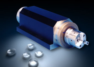
The above developments have been used to design a wide range of high precision spindles of which the following are examples. Contact Lens Turning Spindle - Fig 2 shows an example of a contact lens turning spindle. The requirement is to generate an axisymetric lens form by single point turning and achieve a surface finish needing only a minimum of polishing in a subsequent operation. In this application the workpiece is easily deformable and the use of an air operated chuck allows gripping force to be accurately controlled by air pressure. Furthermore a non contacting air slip ring arrangement built into the spindle enables automatic chuck operation and hence rapid work change over. Chuck jaw relocation accuracy is better than 1 um. The aerostatic bearing arrangement provides overall spindle stiffnesses of more than 35 and 7 N/um in axial and radial directions respectively and generates an asynchronous motion error of less than 0.05 um peak-peak. The spindle is driven by an integral, air cooled 300 watt AC induction motor. Maximum speed is 10 000 rpm, limited by centrifugal force acting on the chuck jaws. Surface finishes achieved by this spindle are typically better than 0.1 um Ra.
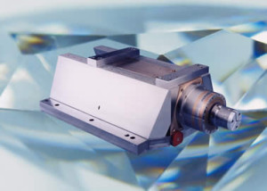
Diamond Turning Spindle - Fig 3 is an example of a diamond turning spindle with integral air bearing slideway. The requirement is to generate accurate workpiece forms with optical surface finish. The form is generated by moving the spindle in an axial direction as the tool moves radially with respect to the axis of rotation. An air bearing slideway has the advantage of no stiction and therefore enables positional accuracies of less than 1 um to be obtained. This spindle also features an air cooled DC brushless motor, high resolution encoder and automatic, dead length collet or air chuck for work holding. Overall spindle stiffnesses are better than 85 N/um and 8 N/um in axial and radial directions respectively. Maximum speed with collet is 12 000 rpm and the use of a DC brushless motor provides a maximum continuous torque of 2 Nm over the relatively wide speed range of 1000 rpm – 12 000 rpm. This spindle achieves surface finishes better than 0.1 um.
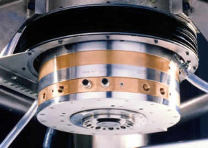
Cup Grinding Spindle - Fig 4 shows a cup grinding spindle fitted to Cranfield University’s Tetraform ‘C’ grinding machine. The machine is required to achieve optical surface finishes from grinding for both brittle materials and hard metallic surfaces at relatively high material removal rates. In terms of spindle performance these requirements demand high static and dynamic stiffnesses and low motion errors over a wide speed range. The spindle has static axial and radial stiffnesses of 400 N/um and 100 N/um respectively and a maximum speed of 6000 rpm. Chilled water cooling of the bearing housing and through the shaft coolant feed also ensures axial thermal growth of the spindle is low and coolant is fed efficiently to the cup grinding wheel. To minimise motion errors the drive motor is a framed DC brushless type fitted to the rear of the spindle. This spindle has been used to grind a variety of materials such as glass, silicon and M50 tool steel. Surface finishes consistently better than 10 nm Ra and as low as 1 nm Ra have been achieved. Concluding RemarkIncremental developments in air bearing technology and the associated manufacturing process has enabled aerostatic spindles to be designed and built to meet a wide range of high and ultra precision machining requirements. Ongoing developments in air bearing technology and auxiliary spindle components are expected to lead to further improvements. Both in the standard of precision that can be reached as well as the range of conditions that can be achieved FAG HCS71916C.T.P4S.UL| FAG HCS71913E.T.P4S.UL | FAG HCS71914C.T.P4S.UL | FAG HCS71912E.T.P4S.UL | FAG HCS71911E.T.P4S.UL | FAG HCS7010C.T.P4S.UL | FAG HCS71906E.T.P4S.UL | FAG HCS7008C.T.P4S.UL | FAG HCS71906C.T.P4S.UL | FAG HCS71905E.T.P4S.UL |


